 |
|
Supervise, Control and Protection System including Remote Visible System and DC Power Supply for Small Plant |
Supervise, Control and Protection System
a. Overview
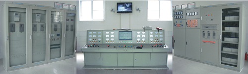
Supervise Control and Protection System (or Micro-Computer Automation System) for Power Station is mainly composed of Micro-computer monitoring system and Micro-computer protection system, which mainly applies to 200MW or below medium and small-sized hydropower or thermal power station and occasions where computer protection and monitoring are integrated or computer protection and monitoring system are relatively independent. The system adopts fully open and layered network conforming to international standard and is a new generation Micro-computer automation system designed for facing object on Windows/Unix and strategy of no-man on duty and less ward. The system can fulfill monitoring, control adjusting and operation management automation for whole station.
Micro-Computer Automation System for Power Station is leading pace in China market and has features of high performance, low price, advanced craft, friendly interface and convenient operation.
b. Typical Design Scheme
According to need of generator protection and monitoring and capacity of unit, recommended design schemes with high performance and competitive price are as follows:
|
Scheme No. |
Diagram No. |
System Structure |
Applicable Capacity
(unit capacity) |
Configuration
Mode |
Note |
|
1 |
1-1 |
integrated |
≤1.0 MW |
Table-2 |
single network (with no PLC) |
|
1-1 |
layered distributed |
≤1.0 MW |
Table-2 |
single network (with PLC) |
|
2 |
1-2 |
layered distributed |
0.5 MW-3MW |
Table-4 |
single network or double unit hot reserve |
|
3 |
1-3 |
layered distributed |
2.5 MW-5MW |
Table-6 |
double unit hot reserve (communication management device set in local layer additionally) |
|
4 |
1-4 |
layered distributed |
5 MW-10MW |
Table-8 |
double unit hot reserve or multi-unit single network |
|
5 |
1-5 |
layered distributed |
10MW-25MW |
Table-10 |
multi-unit single network or multi-unit double network single protection |
|
6 |
1-6 |
layered distributed |
25MW-50MW |
Table-12 |
multi-unit double network single protection |
|
7 |
1-7 |
layered distributed |
50MW-100MW |
Table-14 |
multi-unit double network double protection |
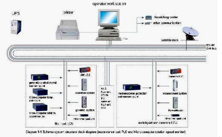
■ Design Scheme-1
□ Application Features
The System Structure is in 3 layers: Main Control, Communication and Local LCU Layer. Configuration is simple and maintenance is convenient because of main control layer adopting single Operator Work Station to fulfill central station operation management. Communication is safe and steady on Communication Layer adopting super anti-interference local communication bus-bar. Local LCU Layer is mainly composed of each local protection and monitoring device, which has powerful function, flexible configuration and steady performance.
□ Application Range
Small-sized unit (unit capacity is ≤1.0MW).
□ System Design Mode
|
Type |
Mode-1 |
Mode-2 |
|
Application Range |
unit capacity≤1.0MW |
unit capacity≤1.0MW |
|
Generator Voltage Class |
0.4KV, 6.3KV, 10.5KV |
0.4KV, 6.3KV, 10.5KV |
|
Typical Mode |
2 unit 1 transformer 1 outlet |
2 unit 1 transformer 1 outlet |
|
System Structure |
integrated |
Layered distributed |
|
System
Configuration |
Main Control Layer |
1 operator work station (option) |
1 operator work station |
|
Communication Layer |
CAN card or serial card, communication line, etc. |
CAN card or serial card, communication line, etc. |
|
Local LCU Layer |
unit control, protection and synchronism device, including unit, main transformer and line protection device |
unit control, protection and synchronism device, including unit, main transformer and line protection device |
|
Communication Mode |
CAN bus communication or serial communication |
CAN bus communication or serial communication |
|
Configuration Mode |
unit control protection cubicle: 2 [1 for 1 unit, secondary equipment is small-sized unit intelligent control system including control, measurement, protection, frequency (active power) adjusting, voltage (reactive) adjusting, synchronize and close and communicate with up-layer device, etc]
Main transformer and line protection cubicle: 1 (option) |
unit control protection cubicle (1 for 1 unit): 2
common LCU cubicle (include synchronism, common device control, etc.): 1 cubicle
main transformer and line protection cubicle: 1 (option, cubicle quantity on configuration and configuration scheme) |
|
System Key Functions |
electrical parameter measurement and switch monitoring, unit automatic control and power adjusting, display, operation maintenance record, event sequence record, print, dispatching communication, system diagnosis |
electrical parameter measurement and switch monitoring, unit automatic control and power adjusting, display, operation maintenance record, event sequence record, print, dispatching communication, system diagnosis |
|
Major Equipment |
400v unit with possible primary equipment, including generator outlet breaker, isolator and current/voltage mutual transformer, unit control, protection measurement, adjusting device, micro-computer temperature patrol monitor, line, transformer micro-computer protection and monitoring device, meter, cubicle |
400V unit with possible primary equipment, master, PLC, temperature patrol monitor, rotation speed monitor, unit micro-computer protection and monitoring device, main transformer micro-computer protection and monitoring device, line micro-computer protection and monitoring device, meter, cubicle |
□ System Structure Block Diagram
The diagram is reference, and actual Local LCU Layer device is decided on power station size and function. The following is system structure diagram:
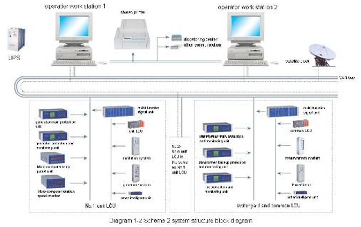
■ Design scheme-2:
□ Application Features
Besides all features in scheme-1, main control layer adopts single or double hot reserve method.
□ Application Range
Unit capacity=0.5MW-3MW.
□ System Design Mode
|
Application Range |
unit capacity: 0.5MW-3MW, total installed capacity: 1MW-10MW |
|
Generator Voltage Class |
6-10.5KV |
|
Typical Mode |
2 unit 1 transformer 1 outlet |
|
System Structure |
Layered distributed |
|
System
Configuration |
Main Control Layer |
1 or 2 operator station |
|
Communication Layer |
CAN card or serial card, communication line, etc. |
|
Local LCU Layer |
1 local LCU device for each unit, PLC as core
1 local LCU for switchyard and common device
1 manual synchronism device for each unit, 1 manual synchronism device for step-up transformer
unit, main transformer, line micro-computer protection and monitoring device |
|
Communication Mode |
CAN bus communication or serial communication |
|
Configuration Mode |
unit LCU: 2; switchyard and common LCU: 1; generator protection cubicle: 1 or 2, main transformer, line protection cubicle: 1 (option) |
|
System Key Functions |
electrical parameter, non-electrical parameter measurement and switch monitoring, unit automatic control and power adjusting, screen display, operation maintenance record, event sequence record, print, dispatching communication, system diagnosis |
|
Major Equipment |
master, PLC, micro-computer temperature patrol monitor, micro-computer rotation speed monitor, synchronism device, unit protection and monitoring device, main transformer micro-computer protection and monitoring device, line micro-computer protection and monitoring device, meter and cubicle body |
□ System Structure Mode
The diagram is reference, actual Local LCU Layer device is decided on power station size and function. The following is System Structure diagram:
■ Design Scheme-3
□ Application Features
System Structure is in 3 layers: Main Control Layer, Communication Layer and Local LCU Layer. Main Control Layer adopts double-unit hot reserve method to fulfill collective management of station running, whose operation is simple and maintenance is convenient. Communication is safe and operation is reliable because of single Ethernet communication adopted in communication layer. The Local LCU Layer is mainly composed of each protection, monitoring device on local, whose has various kinds, powerful functions, flexible configuration and reliable performance.
□ Application Range
Unit capacity=2.5MW-5MW.
□ System Design
|
Application Range |
unit capacity: 2.5MW-5MW, total installed capacity; 5MW-30MW |
|
Generator Voltage Class |
6-10.5KV |
|
Typical Mode |
2 unit 1 transformer 1 outlet |
|
System Structure |
layered distributed |
|
System
Configuration |
Main Control Layer |
1 or 2 operator station |
|
Communication Layer |
exchanger , serial card, communication line, etc. |
|
Local LCU Layer |
1 local LCU device for each unit
1 local LCU for switchyard and common device
1 single-object Micro-computer synchronism device for each unit, 1 multi-object synchronism device for switchyard
unit, main transformer, line Micro-computer protection device |
|
Communication Mode |
Ethernet |
|
Configuration Mode |
unit LCU: 2; switchyard and common LCU: 1;generator protection cubicle: 2 or 1; main transformer cubicle and line protection cubicle: 1 (option) |
|
System Key Functions |
electrical parameter, non-electrical parameter measurement and switch monitoring, unit automatic control and power adjusting, screen display, operation maintenance record, event sequence record, voice alarm, print, dispatching communication, system diagnosis |
|
Major Device |
master, PLC, micro-computer temperature patrol monitor, micro-computer rotation speed monitor, unit micro-computer protection and monitoring device, main transformer micro-computer protection and monitoring device, line micro-computer protection and monitoring device, meter and cubicle body |
□ System Structure Mode
The diagram is reference; actual Local LCU Layer device is decided on power station size and function. The following is System Structure diagram:
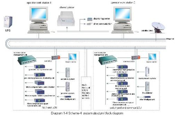
■ Design Scheme-4
□ Application Features
Besides the all application features in scheme-3, Main Control Layer adopts double-unit hot reserve or multi-unit mode, local layer adopts PLC and touch screen mode to guarantee the operation convenient and reliable.
□ Application Range
Unit capacity=5MW-10MW, the occasion where unit (capacity≤5MW) has high requirement and power station has great scale.
□ System Design
|
Application Range |
unit capacity: 5MW-10MW, total installed capacity: 10MW-50MW |
|
Generator Voltage Class |
6-10.5KV |
|
Typical Mode |
2 unit 2 transformer 2 outlet |
|
System Structure |
layered distributed |
|
System
Configuration |
Main Control Layer |
2 operator work station
1 communication work station (option)
1 engineer/training work station (option) |
|
Communication Layer |
exchanger and other network communication device |
|
Local LCU Layer |
1 LCU for each unit, PLC and touch screen as core
1 LCU for switchyard and common device, PLC and touch screen as core
1 single-object micro-computer synchronism device for each unit, 1 multi-object synchronism device for switchyard, main transformer, line and station service transformer micro-computer protection and monitoring device |
|
Communication Mode |
Ethernet |
|
Configuration Mode |
unit LCU: 2; switchyard and common LCU: 1; generator protection cubicle: 2 or 1; main transformer, line and station service protection cubicle: 1 or 2 |
|
System Key Functions |
electrical parameter, non-electrical parameter measurement and switch monitoring, unit automatic control and power adjusting, screen display, operation maintenance record, event sequence record, print, dispatching communication, system diagnosis |
|
Major Equipment |
master, PLC, temperature patrol monitor, micro-computer rotation speed monitor, unit protection and monitoring device, main transformer micro-computer protection and monitoring device, line micro-computer protection and monitoring device, station service transformer micro-computer protection and monitoring device, meter and cubicle body |
□ System Structure Mode
The diagram is reference, actual Local LCU Layer device is decided on power station size and function. The following is System Structure diagram:
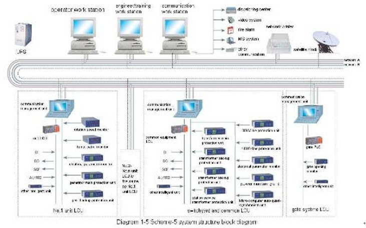
■ Design Scheme-5
□ Application Features
Besides all application features in the above schemes, Main Control Layer adopts multi-unit control, Communication Layer adopts single or double Ethernet communication to improve the communication transmission distance and speed and guarantee the real-time effect and safety and reliability of station running. The Local LCU Layer adopts independent protection and monitoring device. Fulfill No-gap communication connection among Local LCU Layer, Local LCU Layer and Main Control Layer.
□ Application Range
The occasion: unit capacity=10MW-25MW and power station has great scale.
□ System Design Mode
|
Application Range |
unit capacity: 10MW-25MW, total installed capacity: 20MW-100MW |
|
Generator Voltage Class |
≥6.3KV |
|
Typical Mode |
2 unit 2 transformer 2 outlet |
|
System Structure |
layered distributed |
|
System
Configuration |
Main Control Layer |
2 operator work stations
1 communication work station
1 engineer/training work station |
|
Communication Layer |
exchanger and other network communication device |
|
Local LCU Layer |
1 LCU for each unit, PLC and touch screen as core
1 LCU for switchyard and common device, PLC and touch screen as core
1 single-object synchronism device for each unit, 1 multi-object synchronism device for switchyard, unit, main transformer, line protection device
1 LCU for gate control system, PLC and touch screen as core |
|
Communication Mode |
double optical fiber Ethernet communication |
|
Configuration Mode |
unit LCU: 2; switchyard and common LCU: 1 or local control box; generator protection cubicle: 2 or 1; main transformer cubicle and line protection cubicle: 1; station service transformer protection cubicle: 1 |
|
System Key Functions |
electrical parameter, non-electrical parameter measurement and switch monitoring, unit automatic control and power adjusting, screen display, operation maintenance record, event sequence record, voice alarm, print, dispatching communication, system diagnosis |
|
Major Equipment |
master, PLC, touch screen, AC sampling device, micro-computer temperature patrol monitor, micro-computer rotation speed monitor, synchronism device, unit protection device, main transformer protection device, line protection device, station service transformer protection device, meter and cubicle body |
□ System Structure Block Diagram
The diagram is reference, actual Local LCU Layer device is decided on power station size and function. The following is System Structure diagram:
 ■ Design Scheme-6
□ Application Features
System is divided in 3 layers: Main Control Layer, Communication Layer and Local LCU Layer
→Main Control Layer: Multi-units management station-running data central management in Data server; remote operation including remote data inquiry, remote parameter setting, etc; real-time training emulation workstation; real-time station running status monitoring, failure report and real-time print; communication including dispatching center and fire alarm system, video monitoring system, MIS system, etc.
→Communication Layer: Double-network communication structure
→Local LCU Layer: Communication management controller, PLC direct connecting network method, independent protection and monitoring device Local LCU Layer, independent LCU running).
□ Application Range
The occasion: unit capacity is 25MW-50MW and the Power Station has lots of controlled objects.
□ System Design Mode
|
Type |
Mode |
|
Application Range |
unit capacity: 25MW-50MW, total installed capacity: 50MW-100MW |
|
Generator Voltage Class |
≥6.3KV |
|
Typical Mode |
2 unit 2 transformer 2 outlet |
|
System Structure |
layered distributed |
|
System
Configuration |
Main Control Layer |
1 data server, 2 operator work station, 1 communication work station, 1 engineer/ training work station, 1 director work station (option) |
|
Communication Layer |
exchanger and other network equipment and annex |
|
Local LCU Layer |
1 local LCU device for each unit, PLC and touch screen as core
1 local LCU for switchyard and common device, PLC and touch screen as core
1 single-object synchronism device for each unit, 1 multi-object synchronism device for switchyard
unit, main transformer, line and station service transformer protection device
gate control system LCU, PLC and touch screen as core |
|
Communication Mode |
optical Ethernet (optical cycle network or double network) |
|
Configuration Mode |
unit LCU: 2; switchyard and common LCU: 1 (or control boxes);generator protection cubicle: 2; main transformer protection cubicle: 2; line protection cubicle: 1; station service transformer protection cubicle:1; bus-bar protection cubicle: 1 (option); failure oscilloscope cubicle: 1 (option) |
|
System Key Functions |
electrical parameter, non-electrical parameter measurement and switch monitoring, unit automatic control and power adjusting, screen display, operation maintenance record, event sequence record, print, dispatching communication, system diagnosis |
|
Major Equipment |
master, PLC, touch screen, temperature patrol monitor, rotation speed monitor, synchronism device, AC sampling device, unit protection device, main transformer protection device, line protection device, station service transformer protection device, bus-bar protection device, failure oscilloscope device, meter and cubicle body |
□ System Structure Block Diagram
The diagram is reference, actual Local LCU Layer device is decided on power station size and function. The following is System Structure diagram:
■ Design Scheme-7
□ Application Features
Besides all features in scheme-6, include the following features:
→Main Control Layer: Double data server; director work station additionally set to monitor; Web server and firewall.
→Communication: Optical Ethernet Communication (Optical Cycle network or Double Network).
→Double protection redundancies.
□ Application Range
Occasion: unit capacity=50MW-100MW and the Power Station has lots of controlled objects.
□ System Design Mode
|
Type |
Mode |
|
Application Range |
unit capacity: 50MW-100MW, total unit capacity: 100MW-500MW |
|
Generator Voltage Class |
≥10.5KV |
|
Typical Mode |
2 unit 2 transformer 2 outlet |
|
System Structure |
layered distributed (fully independent protection and monitoring system, double protection redundancies system) |
|
System
Configuration |
Main Control Layer |
2 data server, 2 operator work station, 1 communication station, 1 engineer/training work station, 1 director work station, 1 On-call and printer work station, 1 Web server |
|
Communication Layer |
Network device and annex |
|
Local LCU Layer |
1 LCU for each unit, PLC and touch screen as core
1 LCU for switchyard and common device, PLC and touch screen as core
1 single-object microcomputer synchronism device for each unit, 1 multi-object synchronism device for step-up yard
unit, main transformer, line and station service transformer protection device
gate control system LCU, PLC and touch screen as core |
|
Communication Mode |
optical Ethernet communication (optical cycle network or double network) |
|
Configuration Mode |
unit LCU: 1 for each unit; switchyard and common LCU: 1; generator protection cubicle: 1 for each unit; main transformer protection cubicle: 1, line protection cubicle: 2, station service transformer protection cubicle: 1, bus-bar protection cubicle: 1, failure oscilloscope cubicle: 1 |
|
System Key Functions |
electrical parameter, non-electrical parameter measurement and switch monitoring, unit automatic control and power adjusting, screen display, operation maintenance record, event sequence record, print, dispatching communication, system diagnosis |
|
Major Equipment |
master, PLC, touch screen, micro-computer temperature patrol monitor, rotation speed monitor, synchronism device, AC sampling device, unit protection device, main transformer protection device, line protection device, station service transformer protection device, bus-bar protection device, failure oscilloscope device, meter and cubicle body |
□ System Structure Block Diagram
The diagram is reference, actual Local LCU Layer device is decided on power station size and function. The following is System Structure diagram: